Mechanical

Society: ASME Main Category: Mechanical, Mechanical Sub Category: Rail Transportation, Entertainment Era: 1950-1959 DateCreated: 1959 Disneyland Anaheim State: CA Zip: 92803 Country: USA Website: http://www.asme.org/about-asme/history/landmarks/topics-m-z/rail-transportation---2/-115-disneyland-monorail-system-%281959%29 Creator: Wenner-Gren, Axel, ALWEG
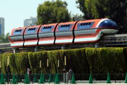
Disney engineers designed this monorail system based on the system developed by Axel Wenner-Gren of the Alweg Company in Cologne, West Germany. Wenner-Gren ran his experimental monorail in 1952 on a level track, and when adopted by Disney in 1959, it was designed to simulate the terrain typical of urban transit. Opening in 1959, the system has been in continuous operation as a passenger service carrying an average of 340,000 passengers a year and logging 10,000 miles. The original trains were replaced in 1969 and a new fleet introduced in 1987 to upgrade the existing chassis.
YearAdded:
1986
Image Credit: Courtesy Flickr/prayitno (CC BY 2.0) Image Caption: Disneyland Monorail System Era_date_from: 1959
Society: ASME Main Category: Mechanical Sub Category: Research and Development Era: 1990-1999 DateCreated: 1996 DLP(r) Demo Center Plano State: TX Zip: 75023 Country: USA Website: http://www.asme.org/about-asme/history/landmarks/topics-m-z/research-and-development/--243-digital-micromirror-device-%281996%29 Creator: Hornbeck, Larry , Texas Instruments
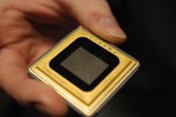
The Digital Micromirror Device (DMD) was recognized as an ASME Mechanical Engineering Historic Landmark in 2008. Its development began in 1977 with the forming of a small team at Texas Instruments headed by noted physicist Larry Hornbeck. Texas Instruments was given a project from the Department of Defense to create a device that could modulate light.
YearAdded:
2008
Image Credit: Courtesy Wikipedia/Adpowers (CC BY-SA 1.0) Image Caption: Picture of DLP chip used in a digital projector at the Cinerama in Seattle Era_date_from: 1996
Detroit Edison District Heating System
Society: ASME Main Category: Mechanical Sub Category: Environmental Control Era: 1900-1909 DateCreated: 1903 2000 Second Street Detroit State: MI Zip: 48226 Country: USA Website: https://www.asme.org/about-asme/who-we-are/engineering-history/landmarks/105-detroit-edison-district-heating-system, https://www.asme.org/getmedia/c43f3200-c9df-4a17-a3f5-5c1d07c87fa5/105-Detroit-Edison-District-Heating-System.aspx Creator: Holly, Birdsill

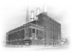
The concept of heating a number of buildings in the core area of a city from a single heating plant was introduced into the United States by Birdsill Holly at Lockport, New York, in 1877. The gain in thermal efficiency of a single large steam plant over a series of small isolated boilers led to widespread commercial installation of district heating. Organized by the Detroit Edison Company, the Central Heating Company began service here in 1903, supplying twelve customers with steam piped from the Edison Company's Willis Avenue Plant. Today's greatly enlarged system continues in operation.
YearAdded:
1985
Image Credit: Courtesy ASME Image Caption: Detroit Edison District Heating System Era_date_from: 1903
Society: ASME Main Category: Mechanical Sub Category: Research and Development Era: 1930-1939 DateCreated: 1939 Taylor Blvd
B
Bethesda State: MD Zip: 20817 Country: USA Website: http://www.asme.org/about-asme/history/landmarks/topics-m-z/research-and-development/-197-david-taylor-model-basin-%281939%29 Creator: Taylor, David
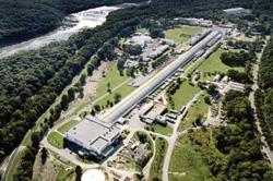
The David Taylor Model Basin is among the largest facilities of its kind in the world, containing a shallow water basin, a deep water basin and a high-speed basin. Using its sophisticated combination of towing carriages, wave makers, and measuring equipment, engineers are able to determine the sea-keeping qualities and propulsion characteristics of ship and craft models up to 40 feet in length. Since it became operational, the facility has provided key support in the development of naval architecture for the Navy, the Coast Guard, the Maritime Administration, and the maritime industry.
YearAdded:
1998
Image Credit: Public Domain (United States Navy) Image Caption: David Taylor Model Basin Era_date_from: 1939
Cruquius Pumping Station
Society: ASME Main Category: Mechanical Sub Category: Pumping Era: 1840-1849 DateCreated: 1849 Cruquiusdijk 27
Haarlemmermeer State: Zip: Country: Netherlands Website: http://www.asme.org/about-asme/history/landmarks/topics-m-z/pumping/-153-cruquius-pumping-station-%281849%29 Creator: Cruquius, Nicolaus Samuel , Beijerinck, Jan Anne

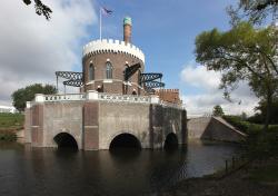
This is one of three nearly identical pumping stations that drained the Haarlemmermeer (Haarlem Lake), 1849- 52, then continued to maintain the polder's water table for more than 80 years. The Haarlemmermeer area covers 45,000 acres (about 70 square miles) in a triangular region between the cities of Amsterdam, Haarlem, and Leiden.
YearAdded:
1991
Image Credit: Courtesy Flickr/Mirko Junge (CC BY-SA 2.0) Image Caption: Cruquius Pumping Station Era_date_from: 1849
Society: ASME Main Category: Mechanical Sub Category: Food Processing Era: 1890-1899 DateCreated: 1892 8801 Citation Road Essex State: MD Zip: 21221 Country: USA Website: http://www.asme.org/about-asme/history/landmarks/topics-a-l/food-processing/-174-crown-cork-and-soda-filling-machine-%281892%29 Creator: Painter, William
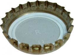
Although bottled carbonated beverages were popular by the 1880s, sealing the bottle was a constant problem. Most "stoppers" were of metal and intended for reuse. None sealed adequately, and contact with the cap often contaminated the drink. In 1892 (Feb 2), William Painter (1838-1906) patented a cheap, single-use metallic cap, crimped over a lip formed on the bottle neck and lined with a thin cork wafer that both formed a leakproof seal and separated drink and metal.
YearAdded:
1994
Image Credit: Courtesy Wikipedia/KMJ (CC BY-SA 3.0) Image Caption: Crown Cork and Soda Filling Machine Era_date_from: 1892
Society: ASME Main Category: Mechanical Sub Category: Manufacturing Era: 1870-1879 DateCreated: 1876 Le Creusot State: Zip: Country: France Website: http://www.asme.org/about-asme/history/landmarks/topics-m-z/manufacturing---1/-69-creusot-steam-hammer-%281876%29 Creator: Schneider and Co.
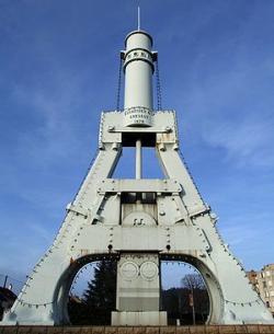
The introduction of steam-powered forging hammers by French and British engineers of the 1830s led to the building of this impressive hammer at Creusot that delivered blows to shape and strengthen iron and steel objects before forging. It was for years the most powerful steam hammer in the world. Yet in 1878 a writer observed that "this formidable mass is capable of ... corking a bottle without breakage." With a striking capacity of 100 tons and a stroke of 5 meters, it worked massive iron and steel shafts, piston rods, and other forgings for fifty-four years, until its retirement in 1930.
YearAdded:
1981
Image Credit: Courtesy Wikipedia/Christophe Finot (CC BY-SA 2.5) Image Caption: Creusot Steam Hammer Era_date_from: 1876
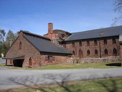
Society: ASME Main Category: Mechanical Sub Category: Minerals Extraction & Refining Era: 1700-1749 DateCreated: 1742 94 Rexmont Rd Lebanon State: PA Zip: 17042 Country: USA Website: http://www.asme.org/about-asme/history/landmarks/topics-m-z/minerals-extraction-and-refining/-106-cornwall-iron-furnace-%281742%29 Creator: Grubb, Peter
When erected by Peter Grubb to smelt the rich iron ore of the nearby Cornwall ore banks, this stone-built blast furnace was typical for its time, producing about 20 tons of pig-iron and cast-iron products a week. A major reconstruction in 1856 to 1857 produced important changes: the furnace itself was enlarged; the blast-air bellows were replaced by a pair of wooden cylinder "blowing tubs"; the waterwheel that had powered them was replaced by a 20-horsepower steam engine; and a pair of waste-heat boilers to supply the engine was built into the open stack of the furnace.
YearAdded:
1985
Image Credit: Courtesy Wikipedia/Wherring (CC BY-SA 3.0) Image Caption: Cornwall Iron Furnace Era_date_from: 1742
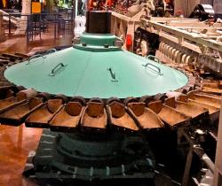
Society: ASME Main Category: Mechanical Sub Category: Manufacturing Era: 1920-1929 DateCreated: 1926 The Henry Ford Museum Dearborn State: MI Zip: 48124 Country: USA Website: http://www.asme.org/about-asme/history/landmarks/topics-m-z/manufacturing---1/-81-corning-ribbon-machine-%281926%29 Creator: Woods, William , Corning Glass Works
While Thomas Edison perfected the first practical and durable filament in 1879, it was not until much later that electricity left the laboratory to become the universal source of light. This required a tremendous number of glass envelopes for light bulbs. In the 1890s the top speed of the finest glass-blowing team produced two bulbs a minute.
YearAdded:
1983
Image Credit: Original Image: Courtesy Flickr/ellenm1 (CC BY 2.0) Image Caption: Corning Ribbon Machine Era_date_from: 1926
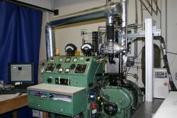
Society: ASME Main Category: Mechanical Sub Category: Research and Development Era: 1920-1929 DateCreated: 1928 Waukesha State: WI Zip: Country: USA Website: http://www.asme.org/about-asme/history/landmarks/topics-m-z/research-and-development/-50-cooperative-fuel-research-engine-%281928%29 Creator: Waukesha Motor Company

The Cooperative Fuel Research (CFR) engine is used extensively throughout the world for testing, research, and instruction in the performance of fuels and lubricants for the internal combustion engine. Principal design work on this prototype engine was accomplished by engineers of Waukesha Motor Company, now a division of Dresser Industries, who served on a Cooperative Fuel Research Committee with representatives of the American Petroleum Institute, Society of Automotive Engineers, Automobile Manufacturers Association, and the National Bureau of Standards.

YearAdded:
1980
Image Credit: Courtesy Colorado State University Image Caption: Cooperative Fuel Research Engine Era_date_from: 1928
Subscribe to Mechanical

We hope you enjoyed this essay.

Please support America's only magazine of the history of engineering and innovation, and the volunteers that sustain it with a donation to Invention & Technology.

Donate

Stay informed - subscribe to our newsletter.
The subscriber's email address.